Routed Network
Consider the following topology where 16.0.0.1 wants to reach 48.0.0.1:
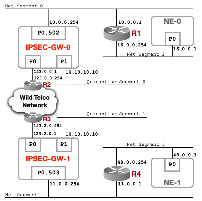
IPsecGW connects multiple network segments. This is a realistic network architecture as found on large scale telco operators networks. IPsecGW are in charge of interconnecting trusted networks segments using and relying on a large network infrastructure referred as "Wild Telco Network" on the picture. This Wild network infrastructure is mostly built using heterogeneous routing equipements and can run multiple transports and routings protocols. In the proposed topology, IPsecGW are routing ciphered traffic via their P0 ports. Lets define 3 types of network segments:
-
Connected Network : Net Segment 0 is the connected network between IPSEC-GW-0 and router R1. Net Segment 1 is the connected network between IPSEC-GW-1 and router R2.
-
Routed Network : Net Segment 2 is routed by R1 and advertised to IPSEC-GW-0. Net Segment 3 is routed by R4 and advertised to IPSEC-GW-1. Most of the time routed networks are advertised using a routing protocol such as BGP. To simplify, we will use simple statics routes in our test scenario here.
-
Quarantine Network : This segment is used as default captive network, where all traffic that doesn't match any IPsec XFRM policies is redirected to. Mainly it is a default route on both IPsecGW to this quarantine network.
When NE-0 wants to reach NE-1, its traffic is routed by router R1 to IPSEC-GW-0, then IPSEC-GW-0 XFRM polices will match the traffic and tunnels it to IPSEC-GW-1, which, after tunnel decap, routes the traffic to router R4 to eventually reach NE-1. Symetric traffic routing applies when NE-1 wants to reach NE-0.
This is where IPsec Tunnel mode is critical for ISPs or any network operator running a large network. Simply because Wild Telco Network is a collection of routers and other network segments. This network architecture simply relies on pure and simple Layer3 routing.
Both IPsecGW are running Nvidia ConnectX-7 NICs.
Quarantine Network discussion
Default route should be avoided as much as possible for security reasons. A way to avoid miss-use of it is to rely on it to steer traffic to a specific network segment. This is typically usefull to redirect untrusted/unauthorized traffic to a captive portal. When a packet doesnt match any IPsec XFRM policies it will simply be routed to dedicated segment hosting infrastructure to handle it.
This is also a good way to not expose IPsec secured network segments. If we are not using a default route and incoming packets are not matching any IPsec XFRM policies, then an ICMP 'destination unreachable' will be generated. This built-in IP stack feature can be used and abused as a way to probe secured network segments. Using a default route all traffic will be handled and operations on Quanratine network can be both passive by simply logging activities or active by handling traffic. Using passive approach can provide a good way to detect miss-configuration.
IPsecGW: network configuration
On both IPsecGW P0 port is used for ciphered traffic and a VLAN is used on P0 for unciphered traffic. VLAN 502 on port P0 for IPSEC-GW-0 and VLAN 503 on port P0 for IPSEC-GW-1.
sysctl -w net.ipv4.ip_forward=1
sysctl -w net.ipv6.conf.all.forwarding=1

ip link set p0 up
ip address add 123.0.0.1/16 dev p0

ip link add link p0 name p0.502 type vlan id 502
ip link set dev p0.502 up
ip address add 10.0.0.254/24 dev p0.502

# Connected network
ip route add 123.2.0.0/16 via 123.0.0.254

# Routed Networks
ip route add 16.0.0.0/8 via 10.0.0.1
ip route add 48.0.0.0/8 via 123.0.0.254

# Quarantine Network
ip link set dev dummy0 up
ip address add 10.10.10.10/32 dev dummy0
ip route add default via 10.10.10.10
sysctl -w net.ipv4.ip_forward=1
sysctl -w net.ipv6.conf.all.forwarding=1

ip link set p0 up
ip address add 123.2.0.1/16 dev p0

ip link add link p0 name p0.503 type vlan id 503
ip link set dev p0.503 up
ip address add 11.0.0.254/24 dev p0.503

# Connected Network
ip route add 123.0.0.0/16 via 123.2.0.254

# Routed Network
ip route add 48.0.0.0/8 via 11.0.0.1
ip route add 16.0.0.0/8 via 123.0.0.254

# Quarantine Network
ip link set dev dummy0 up
ip address add 10.10.10.10/32 dev dummy0
ip route add default via 10.10.10.10
IPsecGW: strongSwan configuration
IPSEC-GW-0 will use 123.0.0.1 IP Address for its IPsec tunnel endpoint and IPSEC-GW-1 will use 123.2.0.1 IP Address for its IPsec tunnel endpoint.
For all strongSwan operations, please refer to the strongSwan documentation, but to start SA, simply run :
IPSEC-GW-0$ sudo swanctl --load-all
IPSEC-GW-0$ sudo swanctl -i --child tnl-0-1
connections {
  tunnel-0-1 {
    local_addrs  = 123.0.0.1
    remote_addrs = 123.2.0.1

    local {
        auth = psk
        id = ipsecgw-0
    }
    remote {
        auth = psk
        id = ipsecgw-1
    }

    children {
      tnl-0-1 {
        local_ts = 16.0.0.0/8
        remote_ts = 48.0.0.0/24
        esp_proposals = aes256gcm128-esn
        mode = tunnel
        policies_fwd_out = yes
        hw_offload = packet
      }
    }
    version = 2
    mobike = no
    reauth_time = 0
    proposals = aes256-sha256-modp2048
  }
}

secrets {
  ike-tnl-0-1 {
    id-1 = ipsecgw-0
    id-2 = ipsecgw-1
    secret = 'TopSecret'
  }
}
connections {
  tunnel-0-1 {
    remote_addrs  = 123.0.0.1
    local_addrs = 123.2.0.1

    local {
        auth = psk
        id = ipsecgw-1
    }
    remote {
        auth = psk
        id = ipsecgw-0
    }

    children {
      tnl-0-1 {
        local_ts = 48.0.0.0/24
        remote_ts = 16.0.0.0/8
        esp_proposals = aes256gcm128-esn
        mode = tunnel
        policies_fwd_out = yes
        hw_offload = packet
      }
    }
    version = 2
    mobike = no
    reauth_time = 0
    proposals = aes256-sha256-modp2048
  }
}

secrets {
  ike-tnl-0-1 {
    id-1 = ipsecgw-1
    id-2 = ipsecgw-0
    secret = 'TopSecret'
  }
}
Wild Telco Network: Emulating using VRF
In order to emulate Wild Telco Network, we can use the following configuration on a Cisco equipment. This configuration will define a VRF to introduce Layer3 routing :
vlan 502-513

vlan 502
  name ipsecgw_trusted_0
vlan 503
  name ipsecgw_trusted_1

vrf context ipsecgw_unciphered
  ip route 16.0.0.0/8 123.0.0.1
  ip route 48.0.0.0/8 123.2.0.1

interface Vlan510
  no shutdown
  vrf member ipsecgw_unciphered
  no ip redirects
  ip address 123.0.0.254/16

interface Vlan512
  no shutdown
  vrf member ipsecgw_unciphered
  no ip redirects
  ip address 123.2.0.254/16

interface Ethernet1/26
  description IPSEC-GW-0-p0
  switchport
  switchport mode trunk
  switchport trunk native vlan 510
  switchport trunk allowed vlan 502,510
  no shutdown

interface Ethernet1/28
  description IPSEC-GW-1-p0
  switchport
  switchport mode trunk
  switchport trunk native vlan 512
  switchport trunk allowed vlan 503,512
  no shutdown
Simulated Environment
This section will define a simulated env to emulate topology as found on production networks. Our LAB Topology can be used as part of a non-regression & validation process and run on a single server hosting multiple NICs (ConnectX-7 here in our example) where each NIC is a VFIO in a dedicated VM.
Our topology will be articulated around 2 main nodes :
- IPSEC-GW: Configurations and features used in production we want to validate.
- Simulated-NE: Set of configurations emulating routings and network env.
Each time we want to change, extend or add a new feature then IPSEC-GW will be used. Simulated-NE configuration is considered to be fixed and will never be altered.
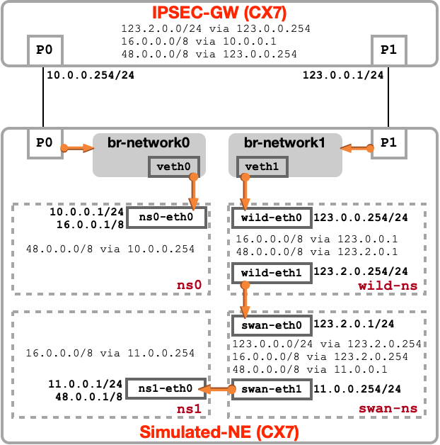
LAB Topology
The LAB topology uses dual-stack IPv4 & IPv6 configurations. For readability reasons, we present the split display in the following 2 pictures:
IPv4 network configuration
IPv6 network configuration
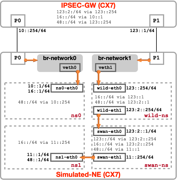
LAB Topology : Network Configuration
To simulate a full routing env within Simulated-NE, we are isolating network segments and functions using Network Namespace. Each physical CX interface will be part of a bridge and VETH interfaces are used as 'cables' for interconnection. Following Network Namespace are created :
- ns0: hosting 16.0.0.0/8 network
- wild-ns: emulating 'Wild Telco Network' by routing endpoints prefixes
- swan-ns: emulating Network running strongSwan IPsec function
- ns1: hosting 48.0.0./8 network
IPSEC-GW node will run a simple routing configuration where un-ciphered traffic are on P0 and ciphered traffic on P1. both endpoint prefixes will be routed to each bridge.
# Enable forwarding
sysctl -w net.core.devconf_inherit_init_net=1
sysctl -w net.ipv4.ip_forward=1
sysctl -w net.ipv6.conf.all.forwarding=1

# Create Virtual-Ethernet cables
ip link add dev veth0 type veth peer name ns0-eth0
ip link add dev veth1 type veth peer name wild-eth0
ip link add dev wild-eth1 type veth peer name swan-eth0
ip link add dev swan-eth1 type veth peer name ns1-eth0

# Create bridge
ip link add br-network0 type bridge
ip link set p0 master br-network0
ip link set veth0 up
ip link set veth0 master br-network0

ip link add br-network1 type bridge
ip link set p1 master br-network1
ip link set veth1 up
ip link set veth1 master br-network1

# Namespace: ns0
ip netns add ns0
ip link set ns0-eth0 netns ns0
ip -n ns0 link set ns0-eth0 up
ip -n ns0 link set dev lo up
ip -n ns0 address add 10.0.0.1/24 dev ns0-eth0
ip -n ns0 address add 16.0.0.1/8 dev ns0-eth0
ip -n ns0 route add 48.0.0.0/8 via 10.0.0.254
ip -n ns0 -6 address add 10::1/64 dev ns0-eth0
ip -n ns0 -6 address add 16::1/64 dev ns0-eth0
ip -n ns0 -6 route add 48::/64 via 10::254
ip link set dev br-network0 up
ip link set dev p0 up

# Namespace: wild-ns
ip netns add wild-ns
ip link set wild-eth0 netns wild-ns
ip link set wild-eth1 netns wild-ns
ip -n wild-ns link set wild-eth0 up
ip -n wild-ns link set wild-eth1 up
ip -n wild-ns link set dev lo up
ip -n wild-ns address add 123.0.0.254/24 dev wild-eth0
ip -n wild-ns address add 123.2.0.254/24 dev wild-eth1
ip -n wild-ns route add 16.0.0.0/8 via 123.0.0.1
ip -n wild-ns route add 48.0.0.0/8 via 123.2.0.1
ip -n wild-ns -6 address add 123::254/64 dev wild-eth0
ip -n wild-ns -6 address add 123:2::254/64 dev wild-eth1
ip -n wild-ns -6 route add 16::/64 via 123::1
ip -n wild-ns -6 route add 48::/64 via 123:2::1
ip link set dev br-network1 up
ip link set dev p1 up

# Namespace: swan-ns
ip netns add swan-ns
ip link set swan-eth0 netns swan-ns
ip link set swan-eth1 netns swan-ns
ip -n swan-ns link set swan-eth0 up
ip -n swan-ns link set swan-eth1 up
ip -n swan-ns link set dev lo up
ip -n swan-ns address add 123.2.0.1/24 dev swan-eth0
ip -n swan-ns address add 11.0.0.254/24 dev swan-eth1
ip -n swan-ns route add 123.0.0.0/24 via 123.2.0.254
ip -n swan-ns route add 16.0.0.0/8 via 123.2.0.254
ip -n swan-ns route add 48.0.0.0/8 via 11.0.0.1
ip -n swan-ns -6 address add 123:2::1/64 dev swan-eth0
ip -n swan-ns -6 address add 11::254/64 dev swan-eth1
ip -n swan-ns -6 route add 123::/64 via 123:2::254
ip -n swan-ns -6 route add 16::/64 via 123:2::254
ip -n swan-ns -6 route add 48::/64 via 11::1

# Namespace: ns1
ip netns add ns1
ip link set ns1-eth0 netns ns1
ip -n ns1 link set ns1-eth0 up
ip -n ns1 link set dev lo up
ip -n ns1 address add 11.0.0.1/24 dev ns1-eth0
ip -n ns1 address add 48.0.0.1/8 dev ns1-eth0
ip -n ns1 route add 16.0.0.0/8 via 11.0.0.254
ip -n ns1 -6 address add 11::1/64 dev ns1-eth0
ip -n ns1 -6 address add 48::1/64 dev ns1-eth0
ip -n ns1 -6 route add 16::/64 via 11::254
# Enable forwarding
sysctl -w net.core.devconf_inherit_init_net=1
sysctl -w net.ipv4.ip_forward=1
sysctl -w net.ipv6.conf.all.forwarding=1

# Local network
ip link set dev p0 up
ip address add 10.0.0.254/24 dev p0
ip -6 address add 10::254/64 dev p0

ip link set dev p1 up
ip address add 123.0.0.1/24 dev p1
ip -6 address add 123::1/64 dev p1

# Connected network
ip route add 123.2.0.0/16 via 123.0.0.254
ip -6 route add 123:2::/64 via 123::254

# Routed networks
ip route add 16.0.0.0/8 via 10.0.0.1
ip route add 48.0.0.0/8 via 123.0.0.254
ip -6 route add 16::/64 via 10::1
ip -6 route add 48::/64 via 123::254
LAB Topology : strongSwan Configuration
The IPSEC-GW node is the only node configured in hw_offload mode. Simulated-NE is configured without offload enabled to inspect ingress and egress ESP traffic. For all strongSwan operations, please refer to the strongSwan documentation, but to start SA, simply run from IPSEC-GW node :
ipsec-gw:$ swanctl --load-all
ipsec-gw:$ swanctl -i --child gw
On Simulated-NE run strongSwan in swan-ns network namespace. For more information about strongSwan & network namespace support please refer to strongSwan in Linux Network Namespaces. We used the following :
simulated-ne:$ mkdir -p /etc/netns/swan-ns/swanctl/conf.d/
simulated-ne:$ cp cx-swanctl.conf /etc/netns/swan-ns/swanctl/conf.d/
simulated-ne:$ ip netns exec swan-ns ipsec start
simulated-ne:$ ip netns exec swan-ns swanctl --load-all
connections {
  B-TO-B {
        #local_addrs  = 123::1
        #remote_addrs = 123:2::1
        local_addrs  = 123.0.0.1
        remote_addrs = 123.2.0.1

        local {
                auth = psk
                id = ipsec-gw
        }
        remote {
                auth = psk
                id = ipsec-enodeb
        }

        children {
          gw {
                #local_ts = 16::/64
                #remote_ts = 48::/64
                local_ts = 16.0.0.0/8
                remote_ts = 48.0.0.0/8
                esp_proposals = aes128gcm128-x25519-esn
                mode = tunnel
                policies_fwd_out = yes
                hw_offload = packet
          }
        }
        version = 2
        mobike = no
        reauth_time = 0
        proposals = aes128-sha256-x25519
  }
}

secrets {
  ike-GW {
        id-1 = ipsec-gw
        id-2 = ipsec-enodeb
        secret = 'TopSecret'
  }
}
connections {
  B-TO-B {
    #local_addrs  = 123:2::1
    #remote_addrs = 123::1
    local_addrs  = 123.2.0.1
    remote_addrs = 123.0.0.1

    local {
        auth = psk
        id = ipsec-enodeb
    }
    remote {
        auth = psk
        id = ipsec-gw
    }

    children {
      gw {
        #local_ts = 48::/64
        #remote_ts = 16::/64
        local_ts = 48.0.0.0/8
        remote_ts = 16.0.0.0/8
        esp_proposals = aes128gcm128-x25519-esn
        mode = tunnel
        policies_fwd_out = yes
      }
    }
    version = 2
    mobike = no
    reauth_time = 0
    proposals = aes128-sha256-x25519
  }
}

secrets {
  ike-GW {
    id-1 = ipsec-enodeb
    id-2 = ipsec-gw
    secret = 'TopSecret'
  }
}
Testing
To validate IPSEC tunnel Packet Offload operations, we send icmp-request from Simulated-NE ns0 IP Address to Simulated ns1 IP Address. This simulates a global routing path via remote IPSEC-GW. The following results MUST be observed:
simulated-ne:$ ip netns exec ns0 ping -I 16.0.0.1 48.0.0.1
PING 48.0.0.1 (48.0.0.1) from 16.0.0.1 : 56(84) bytes of data.
64 bytes from 48.0.0.1: icmp_seq=1 ttl=61 time=0.224 ms
64 bytes from 48.0.0.1: icmp_seq=2 ttl=61 time=0.254 ms
64 bytes from 48.0.0.1: icmp_seq=3 ttl=61 time=0.241 ms
64 bytes from 48.0.0.1: icmp_seq=4 ttl=61 time=0.247 ms
^C
--- 48.0.0.1 ping statistics ---
4 packets transmitted, 4 received, 0% packet loss, time 3101ms
rtt min/avg/max/mdev = 0.224/0.241/0.254/0.011 ms
simulated-ne:$ ip netns exec ns0 ping6 -I 16::1 48::1
PING 48::1(48::1) from 16::1 : 56 data bytes
64 bytes from 48::1: icmp_seq=1 ttl=62 time=0.850 ms
64 bytes from 48::1: icmp_seq=2 ttl=62 time=0.815 ms
64 bytes from 48::1: icmp_seq=3 ttl=62 time=0.821 ms
64 bytes from 48::1: icmp_seq=4 ttl=62 time=0.845 ms
^C
--- 48::1 ping statistics ---
4 packets transmitted, 4 received, 0% packet loss, time 3004ms
rtt min/avg/max/mdev = 0.815/0.832/0.850/0.015 ms
ipsec-gw:$ ethtool -S p1 | grep ipsec
     ipsec_rx_pkts: 37
     ipsec_rx_bytes: 4534
     ipsec_rx_drop_pkts: 0
     ipsec_rx_drop_bytes: 0
     ipsec_rx_drop_mismatch_sa_sel: 0
     ipsec_tx_pkts: 37
     ipsec_tx_bytes: 7118
     ipsec_tx_drop_pkts: 0
     ipsec_tx_drop_bytes: 0
     ipsec_rx_drop_sp_alloc: 0
     ipsec_rx_drop_sadb_miss: 0
     ipsec_tx_drop_bundle: 0
     ipsec_tx_drop_no_state: 0
     ipsec_tx_drop_not_ip: 0
     ipsec_tx_drop_trailer: 0